Introduction:
This article
presents the design and implementation of line follower robot using 8051
Microcontroller. It is programmed to follow a dark line on the white
background and detect turns (or) deviations and modify the motors
appropriately. The path is sensed by the IR
(Infra Red) sensors. The microcontroller controls two DC
motors of robot to navigate through its path.
Basic
Principle:
The basic
principle involved in this is it captures the line position with IR sensors
mounted at front end of the robot. Below
is the block diagram of the line follower robot, when the sensor sense the
path, analog signal is given to the op-amp to produce 0s and 1s which are then
fed to the microcontroller, then the microcontroller decides the next move according
to the program. When both the sensors are indicating low (0) then robot start
moving on the black path, for white if it indicates high (1) then it moves
along the path. Microcontroller and driver circuit are used for the control of
motors.
 |
| Line Follower Robot Block Diagram |
Mechanical parts:
Castor
Wheel - Buy this component from muincept Technologies
Chassis:
Chassis
is the base frame of a car, carriage, or other wheeled vehicle. The rectangular, usually steel frame that holds the body and
motor of an automotive vehicle.

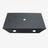
Figure: Chassis
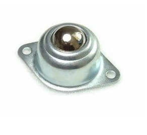
Caster Wheel:
A
Caster
wheel is an undriven, single wheel that is designed to be mounted to the
bottom of a larger object so as to enable that object to be easily moved. They
are available in various sizes, and are commonly made of rubber, plastic,
nylon, aluminum, or stainless steel, etc.

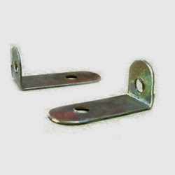
L-Clamp:

Wheel:
Wheel
is a circular object that revolves on an axle and is fixed below a vehicle or
other object to enable it to move over the ground.
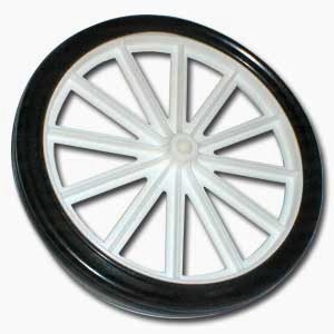

Figure: Wheel
DC
Motor:
DC Motors convert electrical energy (voltage or power source) to mechanical energy (produce rotational motion). They run on direct current.
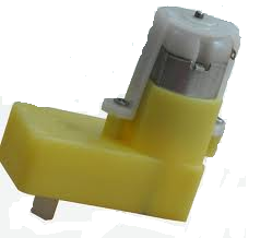
Figure:
DC Motor
Input
and Output devices
Battery Source - Buy this component from muincept Technologies
Voltage regulator - Buy this component from muincept Technologies
Driver IC - Buy this component from muincept Technologies
Microcontroller unit - Buy this component from muincept Technologies
Serial Cable - Buy this component from muincept Technologies
Source:
An ideal voltage source
is a voltage source that maintains the same voltage across the source's
terminals no matter what current is drawn from the terminals of the source or
what current flows into the terminals.
DC
source:
Direct current
(DC) is the unidirectional flow of electric charge. Direct current is
produced by sources such as batteries, solar cells, and commutator-type
electric machines of the dynamo type, etc.
Voltage
Regulator:
Voltage
regulator, any electrical or
electronic device that maintains the voltage of a power source within
acceptable limits.
IC7805
IC 7805 is a 5V Voltage Regulator
that restricts the voltage output to 5V and draws 5V regulated power supply.

Figure:
Pin diagram of IC7805
Sensor
IR reflective sensors have one emitter (IR LED) and one receiver (Phototransistor or photo diode. If we have white surface it reflects the light and it will sensed by the receiver, similarly if we have black surface it absorbs the light and receiver can not sense light.
Photo
diode has property that if IR light fall on it its electrical resistance comes
down (i.e. it comes down from 150kΩ to 10kΩ if no noise present).


Figure:IRSensor
Sample
Calculation:
Say Receiver has resistance
Rs=150kΩ without light (on black surface)
Rs=10kΩ with light (on white surface)
Say Receiver has resistance
Rs=150kΩ without light (on black surface)
Rs=10kΩ with light (on white surface)
The voltage that goes
to comparator Without light: (on black surface)
Vp=(Rs÷(Rs+R))Vcc=150÷(150+10))*5=4.6875V
With light: (on white surface)
Vp=(Rs÷(Rs+R))Vcc=10÷(10+10))*5=2.5000V
Vp=(Rs÷(Rs+R))Vcc=150÷(150+10))*5=4.6875V
With light: (on white surface)
Vp=(Rs÷(Rs+R))Vcc=10÷(10+10))*5=2.5000V
Thus we get variation of voltage that is sensed by comparator IC (LM324).
This gives logical high or low according to input.
Comparator
Comparator is a device which compares two input voltages and gives output high/low. In circuit diagram it is normally represented by a triangle having- Inverting (negative) Input (-),Non Inverting (positive) Input(+), Vcc, Ground, Output.
Use of comparator in IR sensor
As above we see that two inputs are required for comparator. One input is from photo-receiver
(like photo-diode), other is generated by us using potentiometer. The second
voltage is also called as reference voltage for that sensor.
LM358
The
LM358 is a great, easy-to-use dual-channel opamp. LM358 applications include transducer
amplifiers, DC gain blocks and all the conventional opamp circuits.
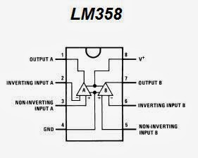
Figure: Pin diagram of LM358
Driver
IC:
L293D is a dual H-bridge motor driver integrated circuit (IC). Motor drivers act as current amplifiers since they take a low-current control signal and provide a higher-current signal. This higher current signal is used to drive the motors. L293D contains two inbuilt H-bridge driver circuits. In its common mode of operation, two DC motors can be driven simultaneously, both in forward and reverse direction. The motor operations of two motors can be controlled by input
logic at pins 2 & 7 and 10 & 15. Input logic 00 or 11 will stop the corresponding motor. Logic 01 and 10 will rotate it in clockwise and anticlockwise directions, respectively.
Enable
pins 1 and 9 (corresponding to the two motors) must be high for motors to start
operating. When an enable input is high, the associated driver gets enabled. Similarly,
when the enable input is low, that driver is disabled, and their outputs are
off and in the high-impedance state.

Figure:
Driver IC L293D
Microcontroller:
Microcontroller acts as the Brain of robot, which generates desired output for corresponding inputs. In present days, there are several companies that manufacture microcontrollers, for example ATMEL, Microchip, Intel, Motorola, Philips etc. We will be using P89V51RD2 microcontroller in our robot. It is a PHILIPS product.
The
NXP (founded by Philips) P89V51RD2 DIP is a 40MHz, 5
Volt 8051-based Microcontroller with 32 I/O lines is an extremely popular 8051
family of microcontroller available in standard 40-pin DIP package. The microcontroller comes with an on-chip boot loader which
makes it easy to program using the serial port.

Figure: Pin diagram of P89V51RD2 Microcontroller
Software Details:
The program code acts as the decision-maker embedded in the microcontroller i.e. it decides what will be the outputs for particular set of input combination. Programs for the P89V51RD2 series of microcontrollers can be written in assembly (ASM) and C. Keil, Flash magic etc. are some free development software’s for programming the P89V51RD2 Microcontrollers. We are using KEIL for programming. In KEIL we write our C code, after compilation it generates ‘.hex’ file that is hardware level code.
Keil uvision
Keil
C51 is the industry-standard tool chain for all 8051-compatible devices, it
supports classic 8051, Dallas 390, NXP MX, extended 8051 variants, and C251
devices. The µVision IDE/Debugger integrates complete device simulation,
interfaces too many target debug adapters, and provides various monitor debug
solutions.
Code for Line follower Robot:
#include<reg51.h>
sbit sensor1=P1^0;
sbit sensor2=P1^1;
sbit motor1=P0^0;
sbit motor2=P0^1;
void main()
{
sensor1=sensor2=0;
motor1=motor2=0;
while(1)
{
if((sensor1==1)&&(sensor2==0))
{
motor1=1;
motor1=1;
motor2=0;
}
else
if((sensor1==0)&&(sensor2==1))
{
motor1=0;
motor1=0;
motor2=1;
}
else
if((sensor1==0)&&(sensor2==0))
{
motor1=0;
motor1=0;
motor2=0;
}
else if((sensor1==1)&&(sensor2==1))
else if((sensor1==1)&&(sensor2==1))
{
motor1=1;
motor1=1;
motor2=1;
}
}
}
}
}
Flash Magic:
The Flash Magic
utility connects the PC's COM port to the serial port of the MCB2300 and
provides In-System Flash Programming (ISP) support for Intel HEX files.
Serial Cable:
A serial cable
is a cable used to transfer information between two devices using a serial
communication protocol.

Figure: Serial Cable
Drop your comments it you need any clarification
Can you please send me circuit diagram of this project.
ReplyDeleteCan you please send me circuit diagram of this project.
ReplyDeletehttp://4.bp.blogspot.com/-fFMLN551fc4/UnOOlM53GHI/AAAAAAAAAKI/W66WCMxoINQ/s400/robo-block-diagram.png
ReplyDeleteThis diagram is totally wrong. When L293D got the sensor feedback then why will it send them to the microcontroller? The microcontroller is here to get the sensor output and the it will send the signal to motor driver(L293D) IC. Then the IC will turn the motor on/off
Why we use dc
ReplyDeleteWhy we use dc
ReplyDeleteplease can i have the circuit diagram
ReplyDelete